Monday, April 8, 2013

Lab 8. Concave and Convex Mirrors

Introduction

This experiment is designed to examine properties of concave and convex mirror by forming images. 

Procedure
1. Standing in front of concave and convex mirror and examine the properties of them

Data

Convex Mirror
Close to mirror
Further from the mirror (~1 m)
Further from the mirror (~2 m)

Concave Mirror
Close to mirror
Further from the mirror (~2 m)

Discussion

Lab 6. Electromagnetic Radiation Lab

Introduction

This experiment is designed to investigate the behavior of electromagnetic(EM) radiation due to a simple antenna.

Procedure

1. Set up the devices - create the transmitter,receiver.
2. Set up the oscillator frequency of about 30 kHz and turn the amplitude to its maximum.
3. Measure the peak to peak amplitude of the received EM wave as a function of the distance from the transmitter. Move the antenna by 5 cm increments and collect data. 
at 5 cm
at 10 cm
.
.
.
Data


Discussion

Peak to Peak amplitude as a function of Distance


Saturday, April 6, 2013

Lab 10. Measuring a Human Hair


Introduction

This experiment is designed to explore the interference of light using a human hair. The thickness of human hair was measured using two method : characteristic of light interference and micrometer.

Procedure

1. Tape a hair cross the punch hole of a card.
2. Mount the laser toward the white board through the hole. -> measure the distance from the card to the wall, marked the minima on the white board.


3. Measure the thickness of same hair using micrometer

Data/Discussion

Conclusion

By comparing value from micrometer measurement with light measurement, the light interference gave very accurate results. 

Thursday, April 4, 2013

Lab 9. Lenses

Introduction

This experiment is designed to explore the relationship between object distance and image distance. Also, explore the magnification change of these images and examine the type of images changing over distance. 

Procedure

1. Find the focal length of lens.
2. Setup the device
3. Move lens from 5 x focal length toward 1.5 x focal length -> measure the data (image distance, image height)


Data/Discussion

1. Focal Length : 5.4 - 5.7 cm (using average value = 5.55 cm)
3. 


4. We did not see images on the board, because now we are getting the virtual images. By looking through the lens, we observed two images front and back : inverted to each other.
5. 


6. 


7, 8 & 9 


Slope = 0.4781
y-intercept = 0.1742

Conclusion

When objects were located beyond the focal length, we were able to observe a real but smaller images. However when the objects were set up closer than the focal length, we could get a virtual images. The magnification get bigger when the object distance was closer to the focal length. 

Lab 7. Introduction to Reflection and Refraction

Introduction

This experiment is designed to examine the reflection and refraction of light : relationship between incidence angle and reflection angle, and relationship between incidence angle and refraction angle. 

Procedure

1. Set up the light box and semicircular plastic on the protractor. 


2. Move the semicircular plastic (starting 0 degree), measure the incidence angle and reflection angle. 
3. Rearrange the device by turning the direction of semicircular plastic.
4. Move the semicircular plastic (starting 0 degree), measure the incidence angle and refraction angle. 

Data/Discussion


2. 
Discussion
1. a) 0 degree
   b) 0 degree
   c) showing discontinuity of small segment because the light get refraction when they pass through different medium
   d) greater (acrylic block) to lower (air)
2. yes
3 &4. Data
5. 

6 & 7.

Slope = 0.6307 = 1/ index of semicircular plastic
8 & 9. 

10. We were not able to complete all 10 trials. The refraction light disappeared.
11 & 12.

Slope = 1.49 = index of semicircular plastic

Conclusion

The incidence light angle and refraction angle has a linear relationship. Based on the measurement, the index of semicircular plastic comes out to be 1.49.

Lab 5. Sound Wave

Introduction

This experiment designed to examine the properties of sound wave. 

Procedure

1. 
Labpro and microphone setup
2. One person say "AAAAAAAAA" -> collect data (graph will appear automatically)
3. Another person say "AAAAAAAA" -> collect data (also, graph will appear)
4. Collect data for a tuning fork by striking it on a soft object. (normal)
5. Collect another set of data for a tuning fork for a sound that is not as loud as #4.
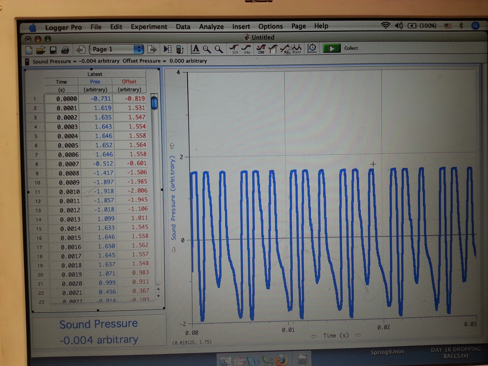
Data

Graph #1
Graph #2
Graph #3
Graph #4
Discussion
C) blinking eye


Increase the sample 10 times long


Conclusion

It was difficult to get a steady wave curve by using human voice. As shown on our graph #1 and #2, the amplitude kept changing. However, the graph created by human voice are a periodic curve which same patterns of peaks were repeated periodically.